 By Elena Mercer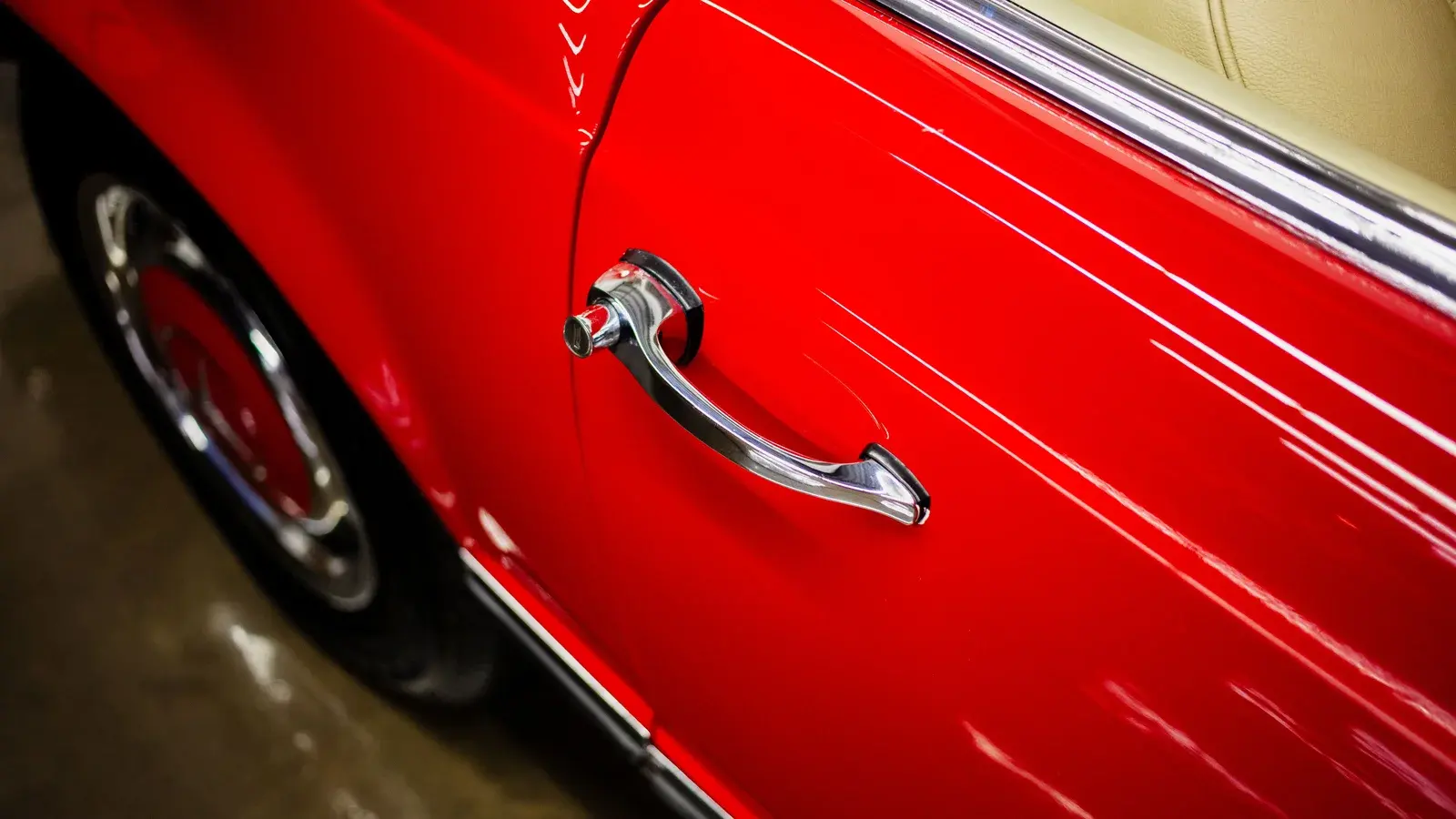
A paint thickness gauge can measure total coating thickness on a compatible panel. An ordinary metal-panel gauge cannot isolate remaining clear coat. Use its readings to document differences and unresolved limits. A displayed number alone cannot approve polishing.
Start with the panel material, the exact gauge model, and its instructions. If any is unknown, hold the measurement-based decision. Confirm the missing information with the vehicle repairer or gauge manufacturer.
Match the gauge to the panel
The substrate is the material beneath the coating. Steel, aluminum, and plastic need different measurement methods. DeFelsko identifies magnetic measurement for steel and eddy-current measurement for aluminum. Eddy current uses an electromagnetic response from conductive metal.
| Panel material | Compatible measurement example | Limit to record |
|---|---|---|
| Steel | PosiTest DFT Ferrous or DFT Combo | Total thickness above the metal; individual layers remain unknown. |
| Aluminum | PosiTest DFT Combo | Ferrous-only instruments cannot provide this measurement. |
| Plastic or fiberglass | A suitable ultrasonic coating gauge | Check the exact probe, finish, geometry, and layer capability. |
| Unknown material or unsupported finish | No assumed compatibility | Identify the panel and ask the manufacturer. Hold the decision. |
DeFelsko lists DFTF for steel and DFTC for steel and aluminum. These examples show compatibility rather than a product ranking. No Detail Compass hands-on comparison was performed.
Some ultrasonic instruments can measure individual layers under supported conditions. DeFelsko describes layer measurements on automotive plastic with the PosiTector 200 B3. Blended layer boundaries and difficult shapes can limit results. Confirm the application instead of assuming every ultrasonic reading isolates clear coat.
Choose the measurement method that supports your actual panels. Leave unsupported locations marked unmeasured.
Separate total film from clear coat
DeFelsko says magnetic and eddy-current gauges measure the distance from the probe to the base metal. That distance includes primer, color, clear coat, and other material above the metal. A thicker reading can warrant investigation, but it does not prove a repair.
A high total can include material beneath the topcoat. It therefore cannot establish extra clear coat available for removal. A low area also needs investigation rather than a universal polishing threshold.
DeFelsko states that there is no absolute correct paint thickness for every automobile. Keep generic factory ranges out of your pass/fail rule. Ask a qualified paint repairer about unexplained readings, damage, and unknown finish history.
Use the conservative one-step polish guide for the separate process and practice checks. Hold abrasive work where the paint condition or measurement interpretation remains unresolved.
Make a repeatable reading record
Check the gauge before using its readings for a decision. The following operating example uses the PosiTest DFT version 4.0 manual. Follow your own instrument manual when the model differs.
- Record the vehicle, date, exact model, serial number, panel material, and selected unit.
- Clean and dry the measurement area. Inspect the probe and finish. Hold work where damage or contamination remains unresolved.
- Check the uncoated compatible metal reference as the manual directs. Place a known-thickness shim flat on that bare metal and measure it. A shim is a thin sheet of known thickness. Do not zero on painted bodywork.
- Obtain the manufacturer-defined acceptance tolerance for that reference and setup. Include the reference or shim tolerance as the manufacturer directs. If the tolerance or reference limits are unknown, hold the decision.
- Record the known value, displayed result, and acceptance tolerance. If the check fails, follow the adjustment instructions and recheck. Ask the manufacturer if it still fails.
- Place the DFT flat and hold it steady until the reading flashes. Lift it for another reading or use its supported repeated-measurement mode. Do not drag the probe.
- Record separate locations and repeat readings. Keep a location sketch or photograph without placing an abrasive mark on the paint.
- Keep individual values and unresolved locations in the log. A whole-panel average can hide the area that needs investigation.
The DFT manual permits zero adjustment on an uncoated part and adjustment against a known thickness. Its supplied shims provide an operational check. If a suitable reference is unavailable, record that limit and follow manufacturer guidance.
Pass: the panel is supported, the reference check passes its applicable tolerance, and units and locations are recorded. Fail: any condition is missing. Resolve it before using the record to make a decision.
This pass confirms the measurement record only. Paint condition and safe material removal still require a separate assessment.
Worked example: readings and uncertainty (hypothetical)
The following readings are invented. Assume a DFT Combo on a supported steel panel, with its reference check completed. All readings use micrometers, written as µm. DeFelsko gives 1 mil as 25.4 µm; a mil is 0.001 inch.
| Hypothetical location | Repeat readings, µm | Record and action |
|---|---|---|
| Door center, point A | 120, 121, 119 | Keep all 3 readings. Mean: 120 µm. |
| Same point after work | 118, 119, 117 | Mean: 118 µm. The displayed difference alone cannot prove removal. |
| Adjacent point B | 85, 86, 84 | Keep this separate lower-reading location. Hold further abrasive work and seek assessment. |
| Plastic bumper | No compatible DFT measurement | Mark unmeasured. Do not assign the door value to it. |
The first mean is (120 + 121 + 119) ÷ 3 = 120 µm. Its unit conversion is 120 ÷ 25.4 = 4.72 mils, rounded. The lower-location mean is 85 µm. That difference identifies a question; it cannot determine the cause or remaining clear coat.
The DFT manual states accuracy as ±(2 µm + 3%). At the hypothetical 120 µm reading, that gives ±(2 + 3.6) = ±5.6 µm. The displayed change between 120 and 118 µm is 2 µm.
That change is smaller than the stated accuracy allowance at either reading. Repeat-location differences add another limit. Do not report 2 µm as confirmed material removal. Averaging readings does not establish a smaller accuracy allowance.
The record passes as a labeled example. It fails as proof of clear-coat thickness or permission for more polishing. Obtain the missing assessment and record the outcome.
Close the inspection record
Download the paint-gauge reading log. Fill its reference check, location readings, unknowns, and action fields for one vehicle. Keep the original readings when adding a follow-up record.
If an unexplained difference remains, stop abrasive work in the affected area. Ask the repairer to assess the finish and document the limits. Choose the service scope only after that assessment.
Review paint protection options after the surface and service scope are established.
The representative stock photo shows a painted car door. Its coating layers, thickness, and repair history were not measured by Detail Compass.
Sources
- How to use paint thickness gauges for automotive detailing — DeFelsko. Checked 2026-10-10. Magnetic/eddy-current total thickness includes all layers; substrate methods, no universal right thickness, units, flat probe and no dragging.
- PosiTest DFT specifications and models — DeFelsko. Checked 2026-10-10. DFTF steel capability and DFTC steel/aluminum capability. Model examples are not comparative tests.
- PosiTest DFT instruction manual, version 4.0 — DeFelsko. Checked 2026-10-10. Page 1: operation, repeat readings, uncoated zero and known-thickness adjustment, shim check, units and accuracy ±(2 µm + 3%).
- Ultrasonic paint thickness measurement on plastic substrates — DeFelsko. Checked 2026-10-10. Compatible ultrasonic measurement and conditional PosiTector 200 B3 layer readings; geometry and blended interfaces limit results.

About Elena Mercer
Elena brings nine years of detailing experience to guides on equipment, pricing, and starting a business.
Meet Elena and read her guides